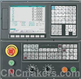
GSK218MD-H CNC Milling Controller
GSK218MD-H CNC milling/machining center controller is widespread CNC system (matched with machining center and general milling machine),employed with 32-bit high performance CPU and super-large-scale programmable device FPGA, real-time control and hardware interpolation technology to ensure the system gets the high efficiency with the μm-level precision, and its PLC can be edit on-line, which makes the logic control function become more flexible and strong.
1.The standard configuration is 4 axes and three links, and the rotary axis is determined by the parameter, and can be adapted with 4 axes link;
2.Max. traverse speed reaches 30m/min, max. feedrate reaches 15m/min;
3. Linear, exponential and S acceleration/deceleration is optional;
4.Pitch error compensation, backlash compensation, tool length compensation, tool wear compensation and tool nose radius compensation;
5. Convenient management with multilevel operation password;
6. Chinese and English display window selected by the parameter
7. 56M program memory capacity to store 400 programs and back stage edit function;
8. standard RS232 and USB interface to realize the bidirectional transmission of programs, parameters and PLC programs between CNC and PC;
9. DNC control and its baud rate can be set, up to 115200;
10. Embedded PLC can realize the various of logic control functions; its ladder can be edit , uploaded and downloaded on-line;
11. standard 48 input/48 output interfaces, I/O can be extended(optional function);
12. Auto/Manual switch by manual interference function;
13. MPG interrupt and Step interrupt function can execute the translation of coordinate system in the course of automatically running;
14. Edit programs can be executed in automatically running;
15. Rigid tapping and soft tapping are set by the parameter;
16. Three-gear shifting function, switch frequency conversion output voltage in max. spindle speed according to the corresponding gear;
17. Rotary, scale, polar coordinates and many kinds of fixed cycle function;
18. Index information function to be convenient to operation and maintenance;
19. History alarm and operation log to be convenient to maintenance.
|
Controlled axes
|
Controlled and linked axes: up to 4 feed axes, one spindle, 3linked axes
|
|
Interpolation method: positioning (G00), linear (G01), arc (G02, G03), helical interpolation
|
|
Max. stroke: metric: ±9999.9999mm, least input increment:0.0001 mm
Inch: ±9999.9999inch, least input increment:0.0001 inch
|
|
Electronic gear: command multiplication coefficient 1~255, command division coefficient 1~255
|
|
Traverse speed: max. 30m/min
Rapid override: F0, 25%, 50%, 100% real-time adjustment
|
|
Cutting feedrate: max. 15m/min (G94) or 500.00mm/r (G95)
Feedrate override: 0~150% divided into 16 levels to real-time adjustment
|
|
Manual feed override: 0~150% divided into 16-level to real-time adjustment
|
|
MPG feed: 0.001mm, 0.01mm, 0.1mm
|
|
Single step feedrate: 0.001mm, 0.01mm, 0.1mm
|
|
Acceleration and deceleration
|
The post acceleration and deceleration can be controlled in Manual mode, and the linear or exponential acceleration and deceleration, and the acceleration and deceleration time constant can be set.
MPG mode can select the instant stop and complete run, and the latter is for the acceleration and deceleration after interpolation, can select the linear or exponential acceleration and deceleration, and the acceleration/deceleration time constant can be set.
Positioning (G00) can select the linear or deflection positioning. The acceleration/deceleration before/after interpolation is optional. The acceleration/deceleration before interpolation is for the linear or S type, and the ones after interpolation is for linear or exponential. And the acceleration/ deceleration time constant can be set.
The system can pre-read most 15 blocks to foreknow the path and speed to get the high speed and smooth of small block, at the same time, it can select Hermit spline interpolation function, applied to the mold machining. The acceleration/deceleration before/after interpolation can be selected in the cutting. The acceleration/deceleration before interpolation can select the linear or S ones, the acceleration/deceleration after interpolation can select the linear or exponential ones, and the acceleration/deceleration time constant can be set.
|
|
M command
|
Miscellaneous function M: Specified by the sequential 2 digits after address M.
|
|
Special M commands (cannot be defined again): end of program M02, M30; program stop M00; optional stop M01; subprogram calling M98; end of subprogram M99.
|
|
M codes are defined by the standard PLC: M03, M04, M05, M08, M09, M10,M11, M12, M13, M16, M17, M19, M21, M22, M32, M33
|
|
G command
|
77 kinds of G command: G00, G01, G02, G03, G04, G10, G11, G15, G16, G17, G18, G19, G20, G21, G22, G23, G24, G25, G26, G27, G28, G29, G30, G31, G33, G34, G35, G36, G37, G38, G39,G40, G41, G42, G43, G44, G49, G50, G51, G53, G54, G55, G56, G57, G58, G59, G60, G61, G62, G63, G64, G65, G68, G69, G73, G74, G76, G80, G81, G82, G83, G84, G85, G86, G87, G88, G89, G90, G91 G92, G94, G95, G96, G97, G98, G99
|
|
T command
|
Tool function: ●T2 digists●256 group tool offset ●tool position offset● tool length compensation ●tool nose radius compensation ● communication input of tool offset value● tool length measurement
|
|
Spindle speed control
|
Spindle function S: ●S 2 digits(I/O gear input and output)/ S 5 digits(analog output)●max spindle speed limit ● constant surface speed
|
|
Spindle encoder: resolutions can be set (100 p/r~5000p/r)
|
|
Transmission ratio between encoder and spindle (1~255):(1~255)
|
|
Automatic compensation
|
●Storage bidirectional compensation of pitch error: compensation points can be set. It is used for compensating the error resulted by machine position (such as the pitch error of the feed screw) to improve the machining precision. The compensated data as parameters are stored in storage.
|
|
●Backlash compensation: it can set the machine’s momentum loss compensated by the fixed frequency or acceleration/deceleration.
|
|
Tool length compensation: it is done by the specified G code (G43,G44,G49); the vertical plane can be selected by parameters.
|
|
●Tool nose radius compensation (G40,G41,G42): C tool compensation
Max. compensation value: ±999.999mm or ±99.9999inch.
|
|
Reliability and safety
|
●emergency stop;●overtravel;●stored stroke limit;●NC ready signal;●servo ready signal ●MST completion signal;●automatic run start light signal;● automatic running signal;●feed hold light signal
|
|
NC alarm: ●program or operation error;●overtravel error;●servo system error;●connection error, PLC error;●storage(ROM and RAM)error;over 300 alarms classified into 5 categories to provide the stable operation and rapid troubleshooting for the system.
|
|
Historic alarm and operation record
|
|
Self-diagnosis function to check the followings: ● system abnormity;● position control abnormity;● servo system abnormity;●RS232 reading abnormity;● PC data transmission abnormity and so on.
|
|
Operation function
|
● dry run ● interlock ● single block ● optional block skip ● Manual absolute ON/OFF ● M.S.T. lock
● machine lock ● feed hold ● cycle start ● emergency stop ● external reset signal ● external power ON/OFF● Manual continuous feed ● incremental feed ● MPG ● skip ●additional optional block skip ● sequence number search ● program number search ● external data input ● program restart ● menu switch ● graphics display● MPG interruption
|
|
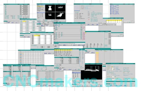
Display
|
●10.4 inch 640×480 chromatic LCD● machine coordinates, absolute coordinates, relative coordinates, residual movement
|
|
● User program ● current operation mode ● system parameter, diagnosis number, alarm number, macro variables, tool offset setting, MDI commands, MST
|
|
State ● actual feedrate, spindle speed ● machining path display ● real-time wave diagnosis
|
|
●System running time and other NC commands and state messages
|
|
Program edit
|
Program capacity: 56M, max. 400 programs, customer macro calling and 4-level subprogram built-in are available
|
|
Background edit, absolute, relative coordinate and complex coordinate programming are supported
|
|
PLC function
|
Control mode: cycle run; processing speed: 3μs/per basic command; max. 3000 steps
|
|
I/O unit :input point/output point: 48/48, expandable
|
|
Development method: PLC commands or ladder
|
|
Command amount: 40 including 10 basic commands, 30 functional commands
|
|
DNC function ALCE
|
Serial DNC, and the baud rate can be set
|
|
Communication
|
Standard RS-232 and USB interface
|
|
Bidirectional transmission of programs, parameters and ladder between CNC and PC
|
|
Optional drive
|
DA98 series digital AC servo drive unit or DY3 series stepper drive unit with input pulse and direction signal
|
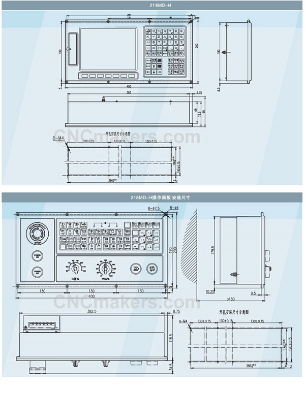
GSK218MD Dimension
GSK218MD Interfaces
 GSK218MC_CNC_Milling_Controller_Programing_And_Operation_Manual.rar GSK218MC_CNC_Milling_Controller_Programing_And_Operation_Manual.rar
GSK218MC_CNC_Milling_Controller_Connectiong_And_Installation_Manual.rar
CNC Retrofit Kit:
http://www.cncmakers.com/cnc/controllers/CNC_Controller_System/CNC_Retrofit_Package.html
|