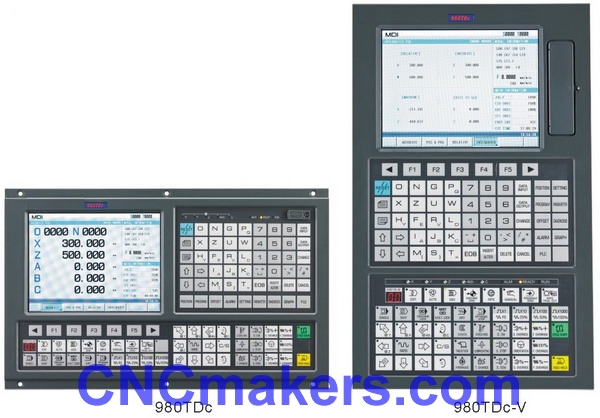
GSK980TDc CNC Lathe Controller
GSK980TDc CNC turning control system from CNCmakers is a new product based on GSK980TDb, and its software and hardware are upgraded,with bigger 8.4'' LCD screen and more powerful built-in PLC which controls 5 feeding axes (including C axis), 2 analog spindles, 2ms interpolation in high speed, 0.1 μm control precision, which obviously improve the efficiency, precision and surface quality of parts processing. New USB interface, it supports the file operation and program running in flash disk. As the upgraded product of GSK980TDb, GSK980TDc is the best choice of CNC lathe for the technical upgrading in economical type. n Five axes of X, Z, Y, 4th and 5th control, the axial name and type of Y, 4th and 5th can be defined. n 2ms interpolation cycle, precision of 1μm or 0.1μm can be selected. n Maximum speed n Adapted servo spindle can realize spindle continuous position, rigid tapping, rigid screw processing n Built-in many PLC programs, the current running PLC program can be selected n G71 command supports the cycle cutting of groove shape outline n Support the programming of macro command in sentence type and the calling of macro program with parameter. n Support programming in metric system/inch system, with function of auto tool-setting, auto chamfering, tool life management. n Display in Chinese, English, Spanish or Russian, which is selected by parameter. n With USB interface, it supports file operation in flash disk, system configuration and software upgrade. n Analog voltage output of 0V~10V in two channels, support double spindles n Electrical MPG input in one channel, it supports hand electrical MPG. n Common input in 40 points/common output in 32 points n Overall installation dimension and the command system are completely compatible with GSK980TDa.
n Number of control axes u Number of control axes: five axes (X, Z, Y, 4th and 5th ) u Number of linkage axes: three axes u Number of PLC control axes: four axes n Feeding axes function u Minimum command unit: u Position command range: ±99999999 × minimum command unit u maximum speed is u Rapid override: Total four levels: F0, 25%, 50% and 100%, real-time adjusting u Feeding override: Total 16 levels: 0~150%, real-time adjusting u Interpolation mode: Interpolation of linear, arc (support arc interpolation of three points), thread, ellipse and parabola and rigid tapping. u Auto chamfering n Thread u Common thread (follow the spindle)/rigid thread u Single-headed/multiple thread of straight, taper and terminal surface in metric system/inch system, equal and variable pitch thread u Thread retraction length, angle and speed characteristics can be set u Thread pitch: n Acceleration and deceleration function u Cutting feeding: Linear type or index type is selectable. u Rapid traverse: Linear type or S type u Thread cutting: Linear type or index type is selectable. u The starting speed, finishing speed and time of acceleration and deceleration are set by the parameter. n Spindle function u Analog voltage 0V~10V output in two channels, support two-spindle control. u Spindle encoder feedback in one channel, the resolution of spindle encoder can be set(100p/r~5000p/r). u The transmission ratio between encoder and spindle is: (1~255):(1~255) u Spindle speed: It is set by S code or PLC signal, the speed range is 0rpm~9999rpm. u Spindle override: Total 8 levels: 50%~120%, real-time adjusting u Spindle constant surface speed control u Rigid tapping n Tool function u Tool length compensation u Tool nose radius compensation (C type) u Tool wearing compensation u Tool life management u Method of setting tools: Tool-setting in fixed position, trial cutting tool-setting, return to reference point, auto tool-setting u Tool offset executing mode: Rewriting coordinate mode, tool traverse mode n Precision compensation u Backlash compensation u Pitch error compensation in memory type n PLC function u PLC program in two levels, maximum 5,000 steps, the refresh cycle of the 1st level program: 8ms u PLC program communication download u Support PLC warning and PLC alarm u Support many PLC programs (maximum 16), the current running PLC program can be selected u Basic I/O: input in 40 points/output in 32 points n Man-machine interface u 7.4″large screen LCD, the resolution is 234×480 u Display in Chinese, English, Spanish or Russian, etc u Display in two-dimensional tool path u Real-time clock n Operation management u Operation mode: Edit, auto, MDI, mechanical zero return, MPG/single step, manual, program zero-return u Operation authority of multiple-level management u Alarm record n Editing program u Program capacity: subprograms, macro programs) u Editing function: program/block/characters research, rewriting and deleting u Program format: ISO code, support macro command programming in sentence type, programming of relative coordinate, absolute coordinate and hybrid coordinate. u Calling program: Support macro program with parameter, subprogram nesting of 4 layers. u Community function u RS232: Files of part program and parameter, etc can be transmitted in two-way, support PLC program, serial ports of software upgrade. u USB: File operation and file directly processing in flash disk, support PLC programs, flash disk of software upgrade. n Safety function u Emergency stop u Hardware travel limit u Software travel limit u Data restoring and recovering
G command table
Macro command list
Configuration Software and Communication Software GSK980TDc uses the same configuration software GSKCC and communication software TDComm2, which run in WINDDOWS98 /2000/XP. GSKCC can edit ladders, part programs, parameters, pitch error compensation data and tool compensation data, and complete the upload and download files and data between PC and GSK980TDb. TDComm can bidirectionally transmit part programs, parameters, pitch error compensation data and tool compensation data between PC and CNC.
Standard Accessories:Switch power: GSK-PB2(assembled at the back of CNC)
Connector assembly: CNC interfaces are connected by one set of plug( DB9 female×2,
DB15 male×3, DB25 female×1, DB25 male×1) Note: Corresponding plugs along with
cables are supplied when they along with other components including drive unit unit
are delivered. Accessory cables: 12m 10-core shield cable (3m for each X axis, Z axis,
input interface XS40/ XS41, output interface XS39/ XS42); 9m 8-core shield cable
(3m for each spindle encoder, input interface XS40/ XS41, output interface XS39/ XS42);
3m 4-core shield cable (inverter interface); Note: The above-mentioned cables as
wires are supplied. Signal cables with welded plugs are supplied when a whole set of
drive unit and tool post controller is delivered. The requirements for cable length and
welding should be remarked in the order list.
Optional Accessories
Communication cable A: serial communication cable 5m×1 between PC
and GSK980TDc (for end user and machine tool manufacturer)
Communication cable B: serial communication cable 5mx1 between
GSK980TDc and PC (for machine tool manufacturer used for installing
and debugging the system)
Communication disc: communication software TDComm installation disc ×1
Ladder programming software: GSKCC installation disc ×1 MPG: Dongxin
RE45T1S05B1 (option: AP01) OR Changchun LGF-001-100(OPTION: AP02);
Additional panel:AP01(aluminum alloy 420mm×71mm) can be assembled
under of GSK980TDc
operation panel;
AP02(aluminum alloy 100mm×260mm)can be assembled at the side of
GSK980TDb operation panel; Emergent stop button: LAY3-02ZS/1 (it has been installed when
GSK980TDa-B is delivered);
No self-locking button: KH-516-B11 (green or red); Self-locking button: KH-516-B21 (green or red); I/O transfer terminal block: MCT 03 Note: one set of I/O transfer cable (with 26-core shield cable,
DB25 male/female socket) when MCT03 is matched
GSK980TD Series CNC PLC User Manual ×1
Note: Optional accessories as product ones (without being
installed and connected) are supplied and it should be remarked
in the order list when they are required to install and connect.
Order Remarks in order:
1 1. Product type(GSK980TDc, GSK980TDc-B), number
2 2. Type and number of assembly (drive unit, isolated transformer)
3 3. Length and connection of accessory cable
4 4. Name, type, quantity, installation & connection requirements of
optional accessories
5 5. Whether PLC program(ladder) is provided according to special
requirement
|
 |
| Products Catalogue | Home | About Us | Retrofit | Download | News | Tech Support | Contact Us | |
|
|
|

