We know that whether it is software programming or manual programming, a program is nothing more than two major components:
1. G command.
2. Point coordinates.
There are dozens of CNC G commands commonly used, but a few, but whether the part is a straight line, arc, or curved surface, it is composed of countless small points, and then the points are connected by small line segments. Up, thus forming a variety of products.
Then when programming, if the data processing of these points is very much, the contour of the processed part will be smooth.
For example, as shown in the figure below, there are several holes on a box, and the inner hole and the arc of the hole bottom must be machined on the CNC machining center (the part circled in red)
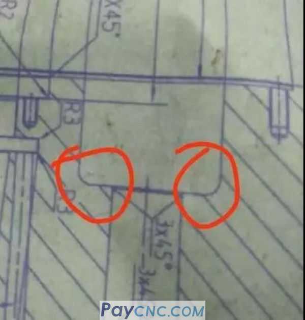
The machining of the arc at the bottom of the hole is very easy to handle. You can make a milling cutter with R just like the arc R of the part. It can be made by spiral interpolation milling, including the unevenness of the bottom of the hole. This procedure is very simple.
But the problem is that the arc R at the bottom of the hole is different. Can the program mill the arc R at one time after the hole is milled by spiral interpolation? This did not catch the knife mark.
If you know macro programming, it's very simple. The program is streamlined, and more importantly, the program has good versatility. One program can satisfy any hole processing.
So how to write a macro program?
Today I will share with you the core idea of writing a macro program: the reasoning of variable relations
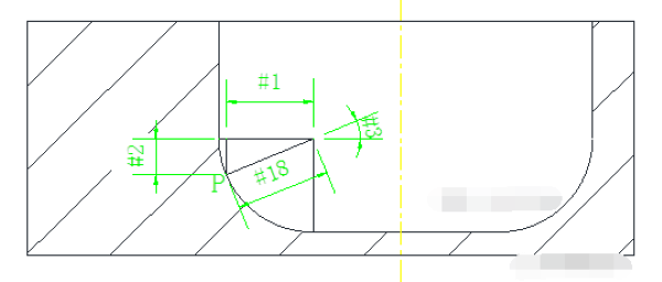
For example, the following is an enlarged simplified diagram of arc R:
Do you remember what Jun Brother said above: Parts are composed of decimal points, and then the points are connected by small line segments. If the data processing of these points is very intensive, then the contour of the processed part will be smooth.
As shown in the figure above, let P be any point on the arc, and use variables to calculate the coordinate value of point P.
How to derive the coordinates of point P? Use mathematical trigonometric functions.
Regarding trigonometric functions, in a right triangle, there will be a relationship between angles and sides, as shown in the following figure:
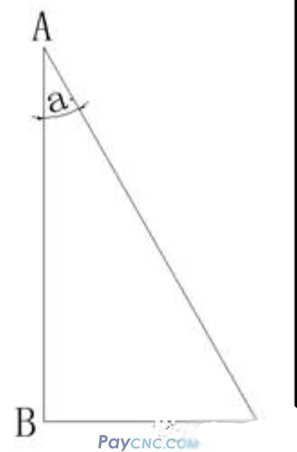
Assuming that the degree of ∠a and the length of side AB are known, how to find the side length of BC and AC?
According to the known conditions, the following corner and side formulas can be derived:
sin a=BC/AC cos a=AB/AC tan a=BC/AB
According to the above formula, the side lengths of BC and AC can be easily calculated. For example, find the AC side length. According to the formula cosa=AB/AC, AC=AB/cosa can be calculated
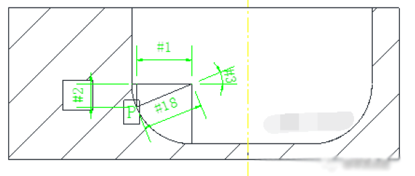
Then make a right triangle in the arc, as shown in the figure above.
According to the trigonometric function formula, the following relationship can be obtained:
#1=#18*COS[#3] (X)
#2=#18*SIN[#3] (Z)
With the relational expression, you need to know #18 and #3 to find #1 and #2.
1. About #18
#18 represents the arc R to be processed, which is a known value. For example, if the drawing needs to be processed R5.1, then
You can assign 5.1 to #18, that is, #18=5.1
2. About #3
#3 represents the included angle. During processing, the angle #3 changes gradually, that is, the P point gradually increases from 0 degrees to 90 degrees. The angle gradually increases, such as #3=#3+5, the smaller the value added later, the denser the P point, and the smoother the arc processed by the programmed program.
Okay, knowing the two data #18 and #3, we have calculated #1 (X-direction value) and #2 (Z-direction data).
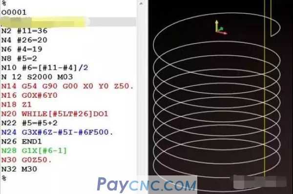
The procedure is as follows:
…….
#3=0
#18=5.1
WHILE[#3LT90]DO1
#1=#18*COS[#3]
#2=#18*SIN[#3]
…….
Machining arc program
…….
#3=#3+1
END1
%
Description:
1. Angle variable #3=0 starts. When #3 is less than 90, the block between WHILE and END will be cycled all the time, that is, the cycle processing 【arc block】.
2. Through the self-increment operation of variable #3, when the value of variable #3 exceeds 90, the cycle ends, that is, the arc processing is completed.
So how to write a program for machining arcs?
The calculated #1 and #2 are centered on the processed arc R, and most of them are centered on the hole during programming, and the surface of the part is the zero point of Z.
Then it is necessary to further derive the relational expression based on the programming origin.
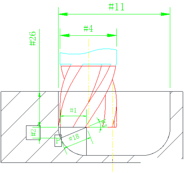
Set #11 as the hole diameter, #4 as the tool diameter, and #26 as the hole depth, as shown in the figure above.
#24=[#11-#4]/2
Then point P
X direction: [#24-#1]
Z direction: [#26+#2]
The relational expression between the variables is thus deduced. With the relational expression, the procedure of machining the arc is very simple.
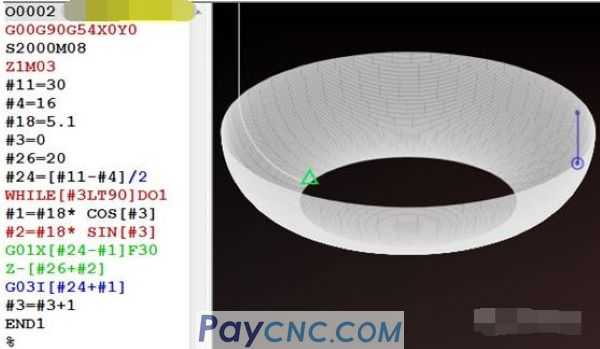
G01X[#24-#1]F30
Z-[#26+#2]
G03I[#24+#1]
With the key blocks, directly copy the program structure mentioned above.
The procedure is as follows:
Well, the case will not be analyzed too much.
Because Jun brother once emphasized that the case is not important, the idea is very important, and the programming method is very important. If you review carefully, how Jun brother developed the relationship between variables step by step.
In fact, a large number of programming skills are applied in the macro program, such as the establishment of mathematical models, the derivation of variable relations, the selection of processing tools, the selection of cutting methods, etc., these are the basic skills that a qualified programming engineer needs to possess.
|
 |
| Products Catalogue | Home | About Us | Retrofit | Download | News | Tech Support | Contact Us | |
|
|
|