 Guangzhou CNC 25i series CNC system alarm "Pv0008 encoder multi-turn data abnormal" alarm, driver GH series 8 # alarm, usually due to low battery voltage caused by the loss of zero data, resulting in related alarms. If this fault occurs, the zero point of the CNC machine tool will be lost, so how do you deal with it after replacing the battery, especially how to adjust after the Z-axis zero point is lost? How to adjust the stroke after resetting the zero point? In the following, we will explain this troubleshooting method by case analysis.
01 Failure phenomenon
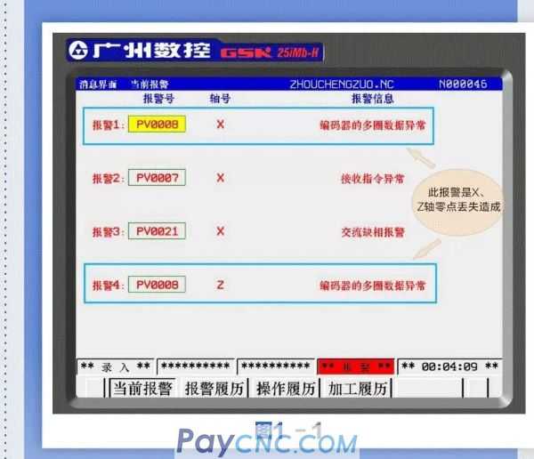
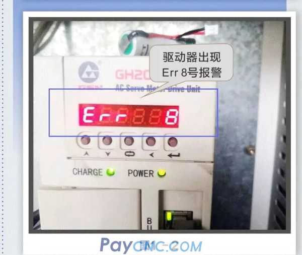
After the GSK25IM-H system is powered on, the PV0008 alarm appears. After opening the cabinet, it is found that the GH2000 driver has an alarm number 8, as shown in Figures 1-1 and 1-2. System alarm.
02 Troubleshooting
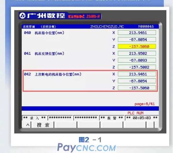
Step 1: Do not power off again after the system is powered on, press the system key to enter the parameter interface, and then press the (Diagnostics) soft key below the screen to enter the system diagnostic interface and search for No. 42, as shown in Figure 2-1, record Diagnose the No. 42 X and Z axis diagnosis data (this data is the machine coordinate before the last power off).
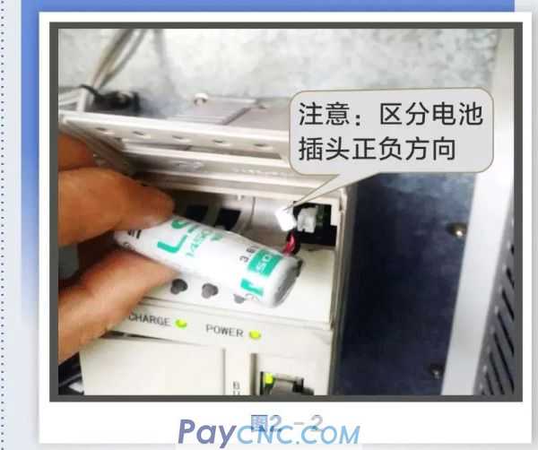
Step 2: The drive is replaced with a new 3.6v battery when the data system is powered on.
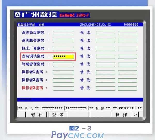
Step 3: Press the bias key to enter the [Login] setting interface, enter the password for installation and commissioning: XXXXXX (consult after-sales technical support staff for specific details), enter the correct password, the corresponding level password will be displayed in red and the relevant parameters can be modified , As shown in Figure 2-3 below.
 Step 4: Press the system key to enter the system parameter interface, search for parameter No. 4001 to enter the interface shown in Figure 2-4 below. In MDI mode, move the cursor to the position parameter corresponding to 4001.3X axis and Z axis respectively, press the number key [0] to set the parameter to 0, press the emergency stop button; then reset the X axis and Z axis corresponding After setting the parameter to 1, press the numeric key [1] to set the parameter to 1, release the emergency stop, and press the reset key. At this time, the alarm details of the system information interface have been eliminated. 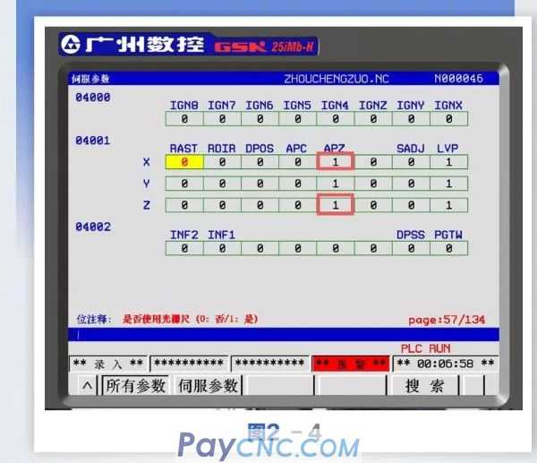
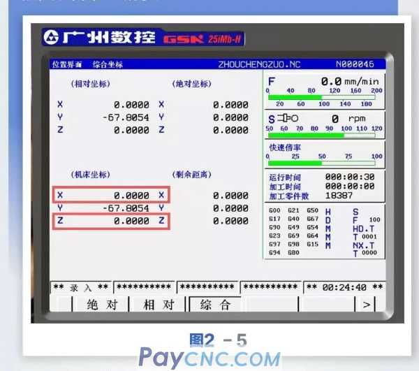
Entering the machine tool position coordinate interface, you can see that the mechanical coordinates of the X and Z axes are "0". At this time, the current position of the machine tool is the new X and Z mechanical zero points, as shown in Figure 2-5 below.
 Step 5: Press the system key to enter the system parameter interface, search for parameter No. 1080 to enter as shown in Figure 2-6. The parameters No. 1080 and No. 1081 are the software limit setting values before the reference points of the three axes of the machine tool X, Y, and Z are not lost. Record the parameter data of No. 1080 and No. 1081. 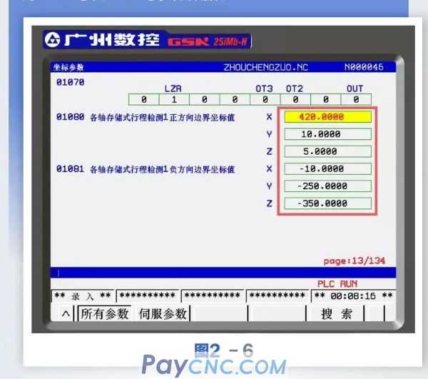 The current machine coordinate position of the X-axis and Z-axis in the fourth step becomes the reference point X0 / Z0 (mechanical zero point), and the X and Z-axis diagnostic data X213.9461 / Z-157.5060 recorded in the first step (this data is The machine coordinates before the last power-off are inconsistent. The goal is to move the X / Z axes to the machine coordinate position X-213.9461 / Z157.5060 by the handwheel to find the original machine zero before the reference point is lost (this operation is very important ), The current moving X, Z axis system will have a software limit alarm, so first change the 1080 and 1081 software limit parameters, that is, change the large stroke to allow the machine tool X, Z axis to move to X-213.9461 / Z157. 5060 position. Switch to MDI mode, and change the software limit parameters No. 1080 and No. 1081 to Z500 / X-1000 as shown in Figure 2-7. 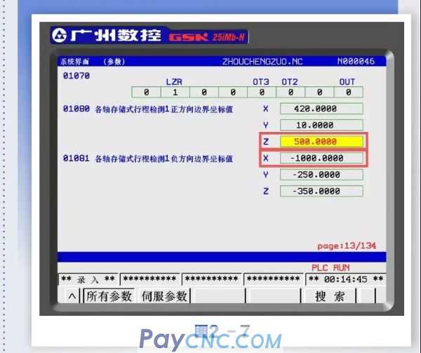
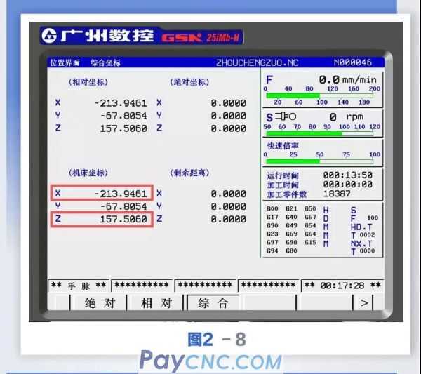
Step 6: Switch to the handwheel mode and move the X and Z axes to the No. 42 X and Z axis diagnostic data X213.9461 / Z-157.5060 recorded in the first step, which is the opposite value of X-213.9461 / Z157.5060 is the machine tool The original X-axis and Z-axis mechanical zero positions are shown in Figure 2-8 below.
Step 7: After the X and Z axes move to X-213.9461 / Z157.5060, repeat the fourth step to reset the current position to the machine zero, and the machine coordinates of the X and Z axes in the position interface will become X0, Z0, the machine tool has recovered to the zero position before the fault.
Step 8: Press the system key to enter the system parameter interface, search for parameters No. 1080 and 1081 and input the original parameter data of No. 1080 and No. 1081 recorded in the sixth step, and restore the X and Z axis software limit parameters of the machine tool. As shown in Figure 2-9. 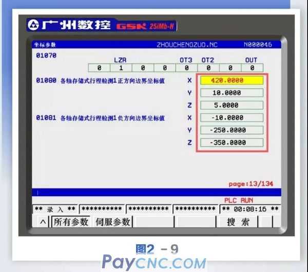
03 Conclusion
Through the above steps, you can quickly solve the problem of low battery voltage and missing reference point, especially the clever use of the system No. 42 diagnostic data value (the commanded position of the last motor bed off) does not need to set the Z-axis second reference point (knife) Library tool change point).
|
 |
| Products Catalogue | Home | About Us | Retrofit | Download | News | Tech Support | Contact Us | |
|
|
|