Detailed introduction to the use of FANUC sub-function
1 Conditions of use
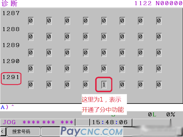
Fanuc's centering function is an optional function. Check whether the machine supports the diagnosis number NO 1291#3=1, which means that the centering function is enabled.
Viewing method: Press the SYSTEM key on the keyboard and select the "Diagnosis" menu at the bottom of the display. (If the diagnosis menu does not appear, press the SYSTEM key again until the diagnosis menu appears)

Then enter 1291, press the search number, the screen shown below appears, 1291#3 is 1, which means that the centering function can be used, and 0 means that it cannot be used
 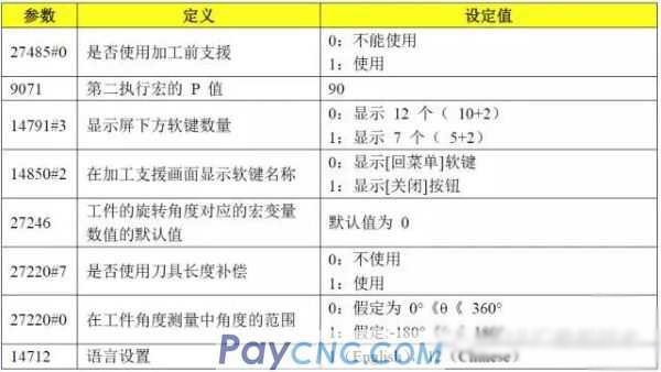
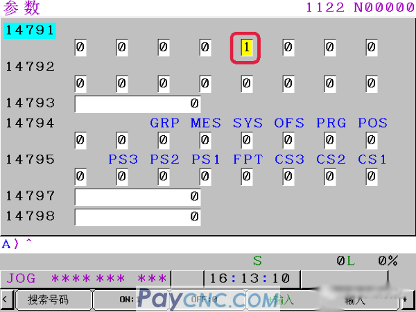
You don’t need to set all the parameters in the above table, generally you only need to set 27485#0, 9071, 14791#3, 14712.
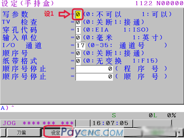
Setting steps: first switch the mode to MDI, press the SET button on the keyboard, select the setting menu, and set the write parameter to 1, as shown in the figure below (after the parameter is set, change this to 0)
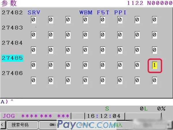
Then press the SYSTEM key on the keyboard, select the "parameter" menu, enter 27485, and then select the "search number" menu, and set as shown below
Then enter 14479, select the search number, and set as shown in the figure below
Use the same method to set the parameters 14712=12, 9071=90, change back to 0 after writing the parameters, and then shut down and restart.
3 Instructions for use
The specific measurement steps are as follows:
1. Select handwheel or manual JOG mode, (must switch mode, automatic MDI and other modes do not display the menu "preparation before processing")
2. Enter the usual tool setting screen, select "Workpiece coordinate system", select "Operation", turn the page to the right twice, and select "Preparation before machining"
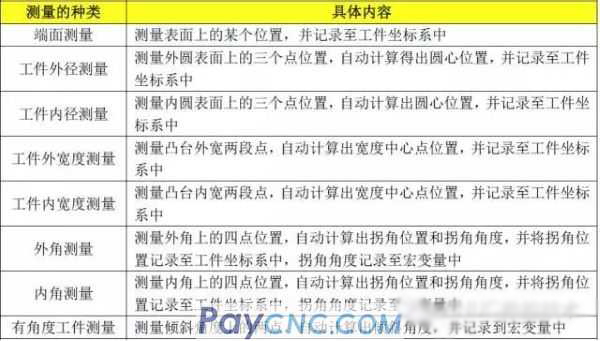
Enter the interface, the functions here are shown in the table below
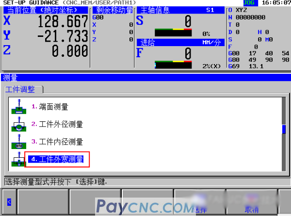
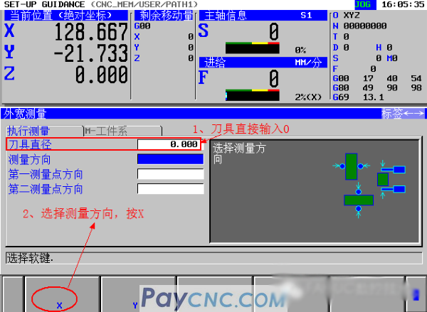
3. Take the centering function as an example, move the cursor, select "4. Workpiece outer width measurement", and press the soft key "Select" button;
4. Enter the tool diameter and measuring direction
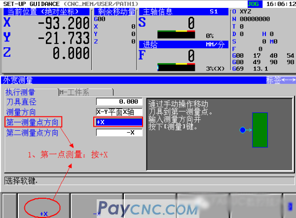
5. Perform measurement (X direction)
 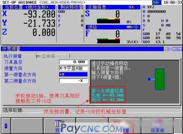 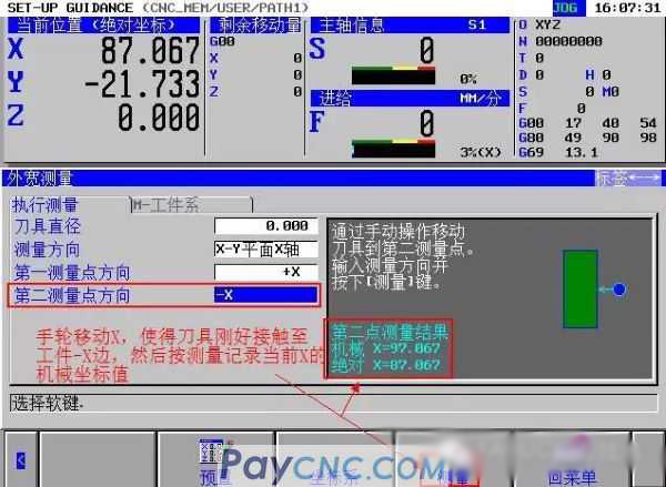
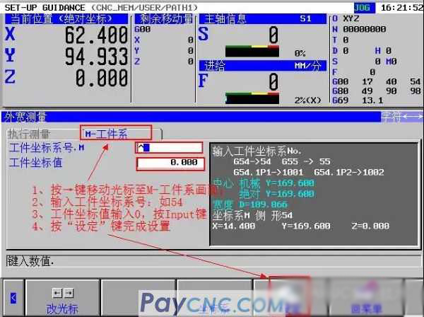
6. Write the measured machine coordinate value into the workpiece coordinate system
① Press the "→" key, move the blue cursor to display "M-workpiece system screen"
② Workpiece coordinate system number: input the workpiece coordinate system to be set, such as G54, input 54 and press INPUT
③ Workpiece coordinate value: input the compensation amount and press the "INPUT" key
④ Press "Set" button to complete the setting
7. Perform measurement (Y direction): consistent with the above steps 5 and 6, and write the Y direction measurement result into the workpiece coordinate system
Examples of finding the center of a circle:
1. Enter the outer diameter measurement screen
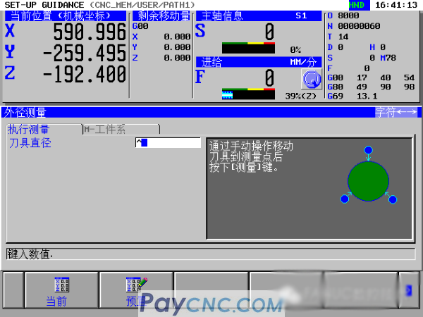
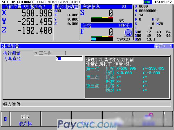
2. To perform outer diameter measurement, move the handwheel to the first point and press "Measure"; similarly, move the handwheel to the second point and press "Measure"; move the handwheel to the third point and press "Measure"
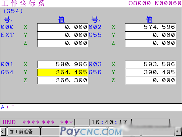
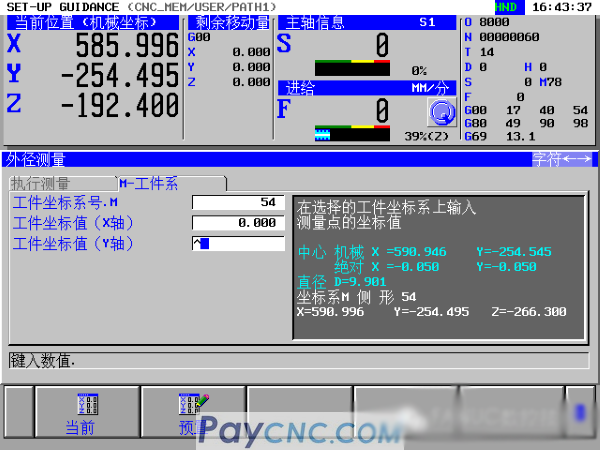
3. Write the workpiece coordinate system
Press "→" to enter the coordinate system selection, select "workpiece coordinate value", enter the compensation amount, and expand to the right, as shown in the figure, press "set".
These two functions are generally used, and the other functions can also be explored and used, but generally not used;
|
 |
| Products Catalogue | Home | About Us | Retrofit | Download | News | Tech Support | Contact Us | |
|
|
|