 01 Tool magazine installation and related PLC parameter settings
Operation purpose: to match the ladder diagram with the configuration of the tool magazine.
The requirements for the machine tool when this ladder diagram is equipped with a bucket-shaped tool magazine:
The machine tool has a spindle tool automatic clamping/loosening device, and the automatic clamping/loosening device is equipped with a normally open in-position detection switch.
The spindle has a positioning function, and the positioning angle can be adjusted.
The capacity of the tool magazine is less than 100.
(The setting value of D100 must be less than 100 and the same as the setting value of CTR100, otherwise an exception will occur.
For example: when D100=16, the data table D001-D016 is valid;
When D100=24, data table D001-D024 is valid. )
The tool magazine can rotate forward and reverse.
The tool magazine has a count switch, a forward in-position detection switch, and a backward in-position detection switch.
The tool magazine has a zero return switch (optional).
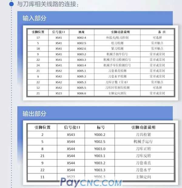
Connection with the relevant lines of the tool magazine:
Precautions
K10.1 and K10.6 must be set according to the actual situation, can not be 1 at the same time.
For example: there is a tool magazine without zero return switch, each detection switch is normally open, and the parameters should be set to:
K010.1=0 K010.2=0 K010.3=0 K010.4=0 K010.5=0
Tool magazine capacity setting:
Enter the tool magazine capacity in DATA100 and CTR100.
Precautions
Tool magazine capacity refers to the number of tool sets that weigh the tool magazine.
The setting values of DATA100 and CTR100 must be less than 100.
For example: when the tool magazine capacity is 16, set DATA100 to 16 and CTR100 to 16.
Precautions
The same tool number (except 0) cannot be set in D001-D099, otherwise an alarm will appear when changing the tool.
The setting range of the tool number needs to meet the requirements set by the parameter 0206, otherwise an alarm will appear when the T code is executed.
For example: when the tool magazine capacity is 24,
If it is set to 1-24 in sequence in D1-D16, when T8M6 is executed, the tool sleeve 8 will be rotated to the tool change position and the tool exchange will be performed;
If set in D1-D16 as 10, 20.30........240 in turn, when T80M6 is executed, the No. 8 tool sleeve will rotate to the tool change position and perform tool exchange;
If both D1 and D2 are set to 8, an alarm will appear when executing T8M6.
02 Manual and zero operation of the tool magazine
Operation purpose: check whether each step of the tool magazine is normal.
The specific steps are as follows:
The tool magazine is effective.
The default state of the system is to use Ladder01.grp ladder diagram, which is the ladder diagram of the bucket-shaped tool magazine. Bit parameters NO:53#0=1, NO:53#1=0, NO:53#2=0, NO:53#3=0. After modifying the parameters, the system needs to be powered off and restarted.
The PLC ladder parameter K001.0 is set to 1.
The tool magazine enters the adjustment mode
PMC ladder parameter K012.7 is set to 1.
In order to facilitate the debugging of the tool magazine gripping position and the concentricity of the spindle and the Z axis tool gripping position, the PMC parameters of the tool magazine debugging can be set. When K012.7 is set to 1, the conditional restriction of the manipulator operation can be cancelled and the tool magazine debugging state can be entered. After debugging, please set K012.7 to 0. The data at this time will not be exchanged.
Under normal circumstances, manually run the robot step
The Z axis returns to the tool change point. (In the input mode, enter G30G91Z0 to return to the tool change point of the robot) Set K10.7 to 1.
Spindle orientation (press the spindle quasi-stop button in manual mode to complete orientation).
The tool holder is vertical (in manual mode, press the tool magazine advance (reverse) button to make the tool holder vertical in place).
Manual manipulator movement to grasp the knife (in manual mode, press the "tool changer" button to complete the manipulator movement 1).
Loosen the knife (in the receiving mode, press the clamping knife/loose knife to loosen the knife and loosen the knife in place).
Manual manipulator movement exchange knife (press the tool changer button again to complete the manipulator movement 2).
Clamping the knife (press the clamping/loosening knife again to tighten the knife and tighten the knife in place).
Move the manual manipulator back to the origin of the manipulator (press the tool changer button for the third time to complete the manipulator movement 3).
The manual manipulator movement is completed.
Under normal circumstances, the conditions for manually running the manipulator: the orientation of the spindle is completed, the tool sleeve is vertically in place, and the Z axis returns to the tool change point.
Determination of the rotation direction of the tool magazine
In manual mode, press the tool magazine counterclockwise button, the tool magazine rotates in the direction of increasing tool number, press the tool magazine clockwise button, the tool magazine rotates in the direction of decreasing tool number, if the opposite phenomenon occurs, the tool magazine count will be disordered, resulting in If the tool exchange is wrong, adjust the phase sequence of the rotary motor of the tool magazine to solve this problem.
Return to zero operation of tool magazine:
The zero return operation of the tool magazine can be divided into two cases with zero return switch and no zero return switch:
When the tool magazine has a zero return switch: Press the tool magazine to return to zero in the "mechanical zero return" mode. When the "tool magazine zero return indicator" is on, the zero return is completed (the light flashes to indicate that the tool magazine is returning to zero).
When the magazine does not have a zero return switch, set the magazine zero point and follow the steps below:
a) In manual mode, press the tool magazine counterclockwise or the tool magazine clockwise button to rotate the tool magazine No. 1 sleeve to the tool exchange position.
b) In the entry mode, set K010.6 to 1.
c) In the mechanical zero return mode, press the tool magazine to return to zero until the "tool magazine return to zero indicator" lights up.
d) Set K010.6 to 0.
03 Manual adjustment after abnormal tool magazine stop
When the manipulator loses power or presses the emergency stop and reset buttons during operation, the manipulator needs to be adjusted back to zero. First set K010.7=1 to make the tool magazine enter the adjustment state, and adjust the manipulator to the zero position according to the above manual operation of the manipulator. If it cannot be eliminated, set K012.7=1 to make the manipulator enter the adjustment state, which is released in this state. All restrictions on the operation of the manipulator need to be operated carefully. After adjusting the manipulator to return to zero, set K010.7=0 and K012.7=0 so that the manipulator can operate normally.
PMC ladder diagram parameter setting instructions:
The zero return operation of the tool magazine can be divided into two cases with zero return switch and no zero return switch:
Enter the system debugging password. Press the Set key, and then press the [Password] soft key to enter the "Setting (Password)" interface. In the entry mode, enter the system debug password, and then press the Enter key. The lower left corner of the screen prompts "Password is correct".
Press the program control key on the MDI keyboard. In the [Ladder Diagram Parameters] interface, press the [Ladder Diagram] soft key to enter the view and setting interface of the holding relay. Press the four direction keys on the keyboard to position the cursor to K010.7 , Press the number "1" key, then press the enter key, then press the save key, the data column prompts: "Ladder diagram downloaded successfully!" means that the save is successful, the tool magazine adjustment mode takes effect. Set K010.7 to 0 to exit the tool magazine adjustment mode.
|
 |
| Products Catalogue | Home | About Us | Retrofit | Download | News | Tech Support | Contact Us | |
|
|
|