 In order to ensure the safe operation of CNC machine tools, the linear axis of the machine tool is usually set with two protection "defense lines": software limit (parameter setting limit) and hard limit (travel switch limit). During the actual use of the 218MC system bus version, since the absolute encoder is used, the limit switch can not be installed, because the hardware limit can be set in [Bus Setting], this alarm is directly generated within the system, if the customer wants to install Hardware limit switches are also available, but these two methods can only choose one of them, and cannot be used at the same time. The pulse version is generally recommended to install a hardware limit switch, so as to ensure safety. The following describes in detail the adjustment method of each axis limit of GSK218MC system:
01 authority login
When setting or modifying software parameters, you first need to obtain the corresponding permissions, as follows:
Press the setting key to enter the setting interface, the cursor moves to the parameter switch, in the input mode, enter 1 to open the parameter switch;
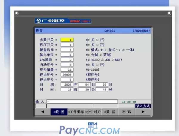
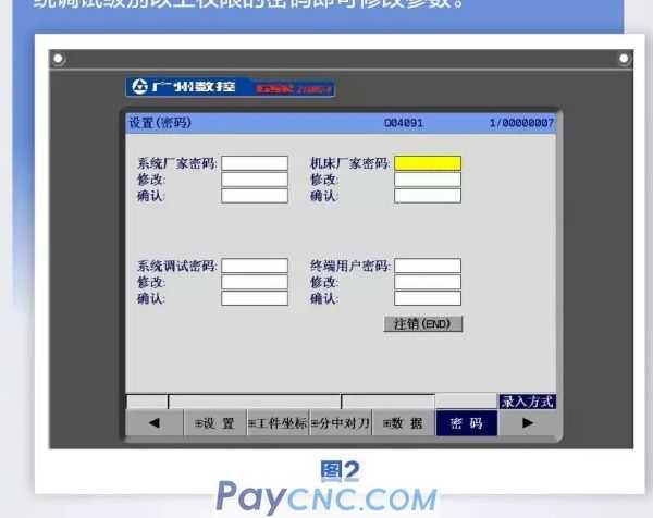
Then press the [Password] soft key to enter the [Setting (Password)] page, enter the password of the system debugging level or higher to modify the parameters.
02 Debugging process of hard limit of each axis
Bus version hard limit setting
Press the system key to enter the system interface, and use the corresponding soft key to switch to display the [+ bus configuration] sub-interface
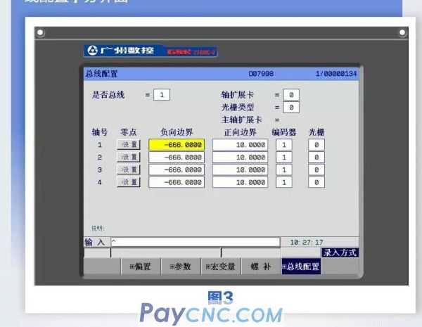
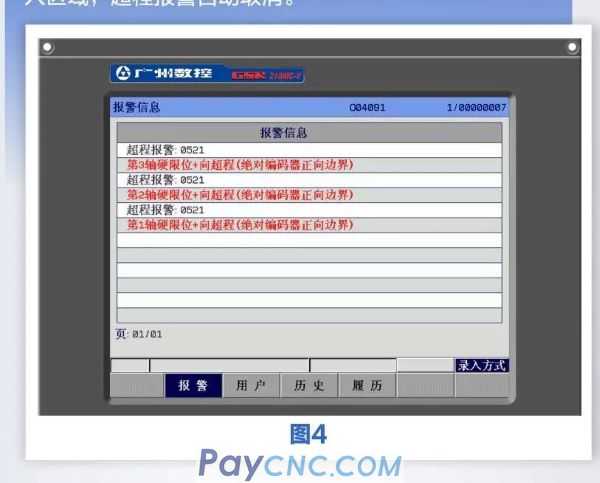
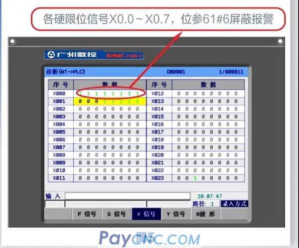
In the input mode, the cursor moves to the setting, press the input key twice, after setting the machine zero, move the yellow block to the positive and negative boundary of the corresponding axis, manually set the negative boundary and positive according to the maximum stroke of the real machine tool To the boundary, the absolute coordinate of the current machine tool is shifted forward or backward by a value, and finally the bit parameter NO.61 # 6 is set to 1, the positive and negative limit is valid. Remove the alarm: As shown in Figure 4, a hardware limit overtravel alarm appears, and the tool can only move in the opposite direction. The tool moves in the opposite direction until it exits the prohibited area, and the overtravel alarm is automatically canceled.
External limit debugging process of each axis
Slowly move each coordinate axis in manual or handwheel mode to verify the effectiveness of each axis's overtravel limit switch, the correctness of the alarm display, and the effectiveness of the overtravel release button; when an overtravel triggers a hardware limit switch, An alarm will appear in the system. Press the overtravel release button and move in the opposite direction to cancel the system alarm. GSK218MC series system provides two connection methods of stroke limit switch to meet user needs.
For safety reasons, the hardware limit switch uses a normally closed contact switch. It is not allowed to install a normally open contact switch. That is, when the external switch is opened, it is considered that the limit point is reached, and an alarm will occur, that is, the corresponding [diagnosis 】 【X signal】 If the corresponding point is 0, it will alarm.
Commissioning of two stroke limit switches
Use two travel switches, that is, one travel switch for each axis's positive and negative direction limit, K6.0 needs to be set to 0, the default value is 0.
Commissioning of single stroke limit switch
Use a single travel switch, that is, use only one travel switch, and use two stoppers to limit the positive and negative limit, you need to set K6.0 to 1, the default value is 0.
Note: When the machine tool is not equipped with a travel switch, please short-circuit the limit switch signal of the corresponding axis to the system + 24V, or set the bit parameter NO: 61 # 6 (whether to ignore the hardware limit alarm) to 1.
03Soft limit adjustment
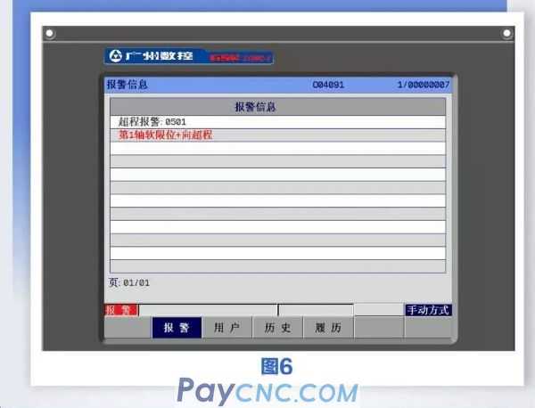
Remove the alarm: As shown in Figure 6, a software limit overtravel alarm appears, and the tool can only move in the opposite direction. The tool moves in the opposite direction until it exits the prohibited area, and the overtravel alarm is automatically canceled.
Storage stroke check 1: The outside of this area is a no-entry area. Machine tool manufacturers often set this area as the maximum stroke of the machine tool.
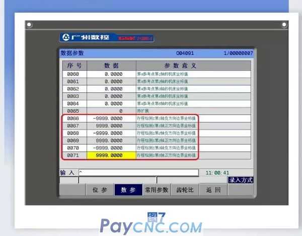
Software limit setting parameters P66-P73: (this parameter is the machine coordinate value), as shown in Figure 7:
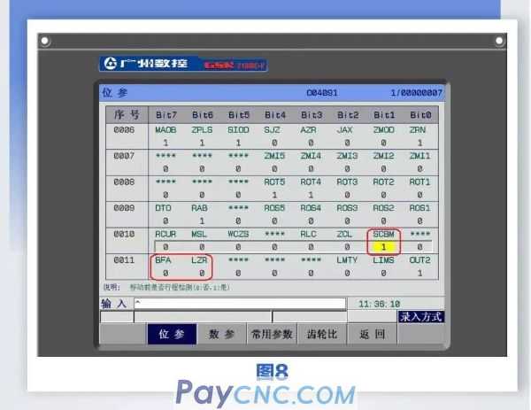
Bit miserable 10 # 1: Whether the stroke detection before moving. As shown in Figure 8, when the program is executed, the system will first pre-read and calculate the coordinates that will be run. Using this function, the position of the overtravel in the subsequent program will be detected during the pre-read, and the system will alarm in advance, without waiting When the program is executed to the alarm line, early alarm saves time.
Bit parameter 11 # 6: Whether the stroke detection is performed after the power is turned on and before the manual return to the reference point (0: not performed, 1: performed). As shown in Figure 8, the software limit is established based on the machine tool coordinates. The incremental machine cannot determine the position of the machine before the machine zero is found. The parameters are used to determine whether the software limit alarm is detected before the machine returns to zero.
Bit parameter 11 # 7: Alarm during overtravel (0: before, 1: after). As shown in Figure 8, select the alarm before overtravel. When the coordinate value of the machine tool when moving the axis reaches or exceeds the first 5mm of the preset parameter, a software limit alarm will be generated for early protection. Alarm is selected after overtravel, and the software limit alarm will only occur when the machine coordinate value is equal to or greater than the set value.
 04 Through the above steps, the system limit problem can be solved at block speed. Guangzhou CNC's 208D system and 990MC system also refer to this method for operation adjustment and elimination. However, it should be noted that the software limit cannot exceed the range of the hard limit, otherwise it cannot play a protective role. |
 |
| Products Catalogue | Home | About Us | Retrofit | Download | News | Tech Support | Contact Us | |
|
|
|