  1. Installation of the support unit on the side of the support base:
1 After the screw shaft is inserted into the single row bearing, it is fixed with a thrust ring.
2
After fixing with the thrust ring, insert the bearing into the support seat.
3
Installation accuracy reference value:
Eccentric tilt
When there is a gap: 20-30μm 1/2000max
Preloaded nut: 15-25μM 1/3000max
High precision requirements: 1/5000max below 10μm
2. Install the ball screw on the workbench and base:
1
First adjust to the installation accuracy reference value.
2
When using the fixed side support unit as a reference, adjust the outer diameter of the nut and the inner diameter of the table nut holder to maintain a certain gap.
3
When using the workbench as a reference, use a thin gasket to adjust the center height for the square support unit, and adjust the outer diameter of the nut and the inner diameter of the workbench nut to maintain a certain gap for the flange type support unit.
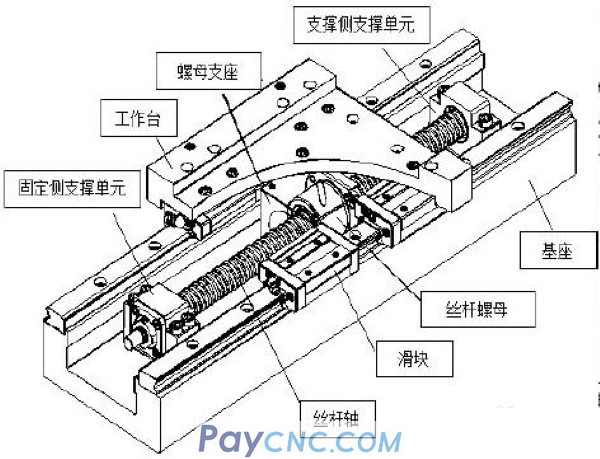
3. Install on the workbench and base:
1
Insert the ball screw nut into the nut support and temporarily tighten it. (Place the nut in the middle of the ball screw shaft)
2
Temporarily fix the supporting units on the fixed side and the supporting side to the base.
3
After moving the workbench and the fixed side support unit, screw the support unit to the base.
4
After fixing, move the worktable to near the end of the stroke near the fixed side, and fix the worktable and the nut support to each other.
5
Fix the nut and nut support.
6
Loosen the bolts for the fourth cloth type, and fix the workbench and the nut support to each other again. Push the workbench to the fixed support unit to adjust its center position so that the workbench can move smoothly. For precision workbenches, the screw shaft needs to be adjusted to a position parallel to the LM guide.
7
After fixing, confirm the operating status of the workbench and move the workbench to the support base.
8
After moving the workbench to the support side support unit, tighten the fixing bolts of the support unit.
9
After fixing, move the workbench to near the end of the stroke near the support side, and loosen the workbench and the nut support again and fix them to each other.
10
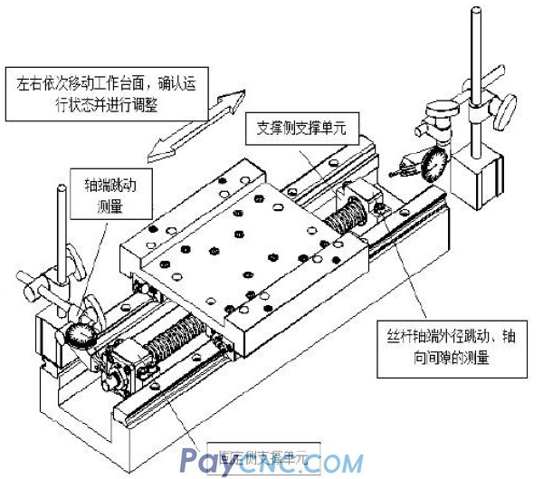
Move the workbench to the fixed side, move it left and right, and confirm the operation status. Move back and forth several times to adjust the worktable to a state where it can run smoothly throughout the entire stroke.
11
If abnormal noise or blockage occurs during operation, please repeat steps 3-10.
Fourth, confirm the accuracy and fully tighten the bolts:
1
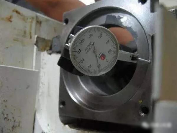
Use a dial gauge to confirm the runout of the outer diameter part of the screw shaft end and the clearance in the shaft direction.
2
Fully tighten the bolts of the nut, nut support, fixed side support unit, and support base fixing unit in turn.
Five, connect the motor:
Install the motor support on the base.
Connect the motor and the ball screw with a coupling.
Full test run.
③The center of the bearing seat hole and the center of the nut support hole of the supporting unit at both ends must be accurately adjusted to the "three-point concentric" state, that is, the centers of the three mounting holes must be accurately adjusted to be in a straight line, and it is not allowed to be in different In the case of forced installation, otherwise it will destroy the accuracy of the ball screw. This is also the reason why the nut support is temporarily not tightened after the ball nut is installed in the previous, because it needs to be carefully adjusted.
④Usually, the linear guide rail and the workbench are assembled first, and the movement direction of the workbench is fixed, and then the direction of the ball screw is adjusted based on this and it is strictly parallel to the movement direction of the workbench. Therefore, before the support unit is finally fixed to the base, the ball nut support and the ball nut are finally fixed, and the ball nut support is finally fixed to the workbench, these four parts should be carefully adjusted to ensure that the support unit , The direction of motion determined by the lead screw and ball nut and the direction of motion of the worktable are adjusted to be strictly parallel in height and left and right directions.
In addition to the assembly method of adjusting the direction of the ball screw based on the direction of movement of the worktable, in some cases, another assembly method is sometimes used, that is, the direction of movement of the fixed ball screw is first assembled, and then adjusted based on this Movement direction of worktable (and linear guide)
It is not allowed to forcibly install the ball nut on the nut support when the direction of the guide rail and the screw are inconsistent, and excessive force cannot be applied during assembly. Because the groove of the screw is quenched and ground, if the screw is combined with the ball nut. Forcibly screwing in will produce indentations on the groove of the screw, reducing the accuracy and life of the mechanism. Cross-threading of the ball nut and the lead screw will also shorten the life.
|
 |
| Products Catalogue | Home | About Us | Retrofit | Download | News | Tech Support | Contact Us | |
|
|
|