How to make me smarter?
How to improve my programming skills?
The method is: drawing
1. What picture should I draw?
Draw tool path diagram
In the article "Zou Jun: Easy to learn CNC macro programming, the secret of becoming a great god with zero basics" I shared this big trick from the machining of turned parts.
Today, from the aspect of milling, I once again emphasize this big trick:
Draw tool path diagram
This big move is already a super big move. However, some people may say that this method is nothing, and they have heard of it a long time ago.
Yes, knowing does not mean it will be effective.
When you draw the tool path diagram, you can visually see the tool path trajectory, so you can look down on the part programming from the perspective of an eagle, and you can also study the details of each step of the tool with the eyes of a mouse.
So how is this trick applied in programming?
Give an example of number milling:
For the following parts, the inner hole with a diameter of D133.2 and a depth of 10 requires machining the bottom plane of the inner hole.
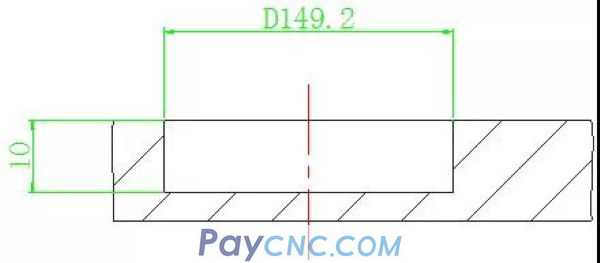 The tool path diagram is as follows: Use spiral interpolation to lower the tool, and then mill to the size from the inside to the outside circle by circle. 
This tool path program consists of two parts:
1. Spiral interpolation cutting program
2. Milling inner hole bottom surface program
I have shared the programming ideas about spiral interpolation milling, so I won’t repeat them here.
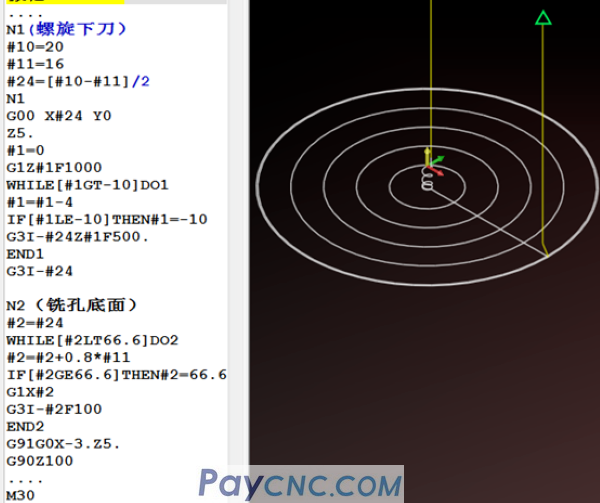
The program of direct upward spiral interpolation milling is as follows:
...
#10=20
#11=16
#24=[#10-#11]/2
N1
G00 X#24 Y0
Z5.
#1=0
G1Z#1F1000
WHILE[#1GT-10]DO1
#1=#1-4
IF[#1LE-10]THEN#1=-10
G3I-#24Z#1F500.
END1
G3I-#24
After the spiral cutting is completed, the tool Z=-10 has been spirally interpolated to the bottom plane of the hole. At this time, a full circle is milled, and then the bottom hole is milled. The tool path is as shown below:
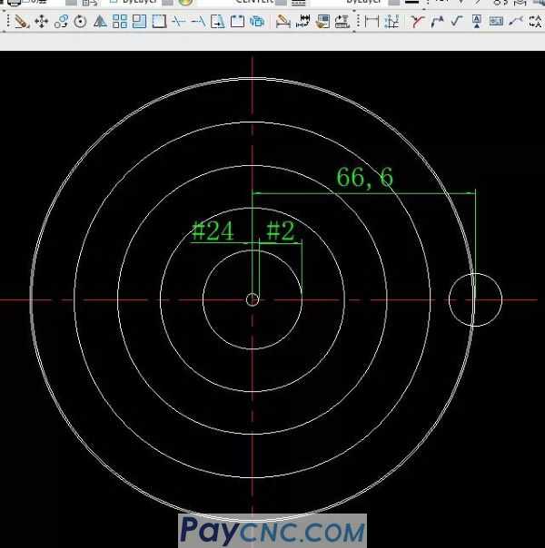
Mill a circle, then X moves a step, then mill a circle, and so on to the final size of the drawing.
From the upper tool path diagram, it is easy to see that the X value is constantly changing.
How does it change?
That is to move one step in the X direction, if the variable #2 is set to represent the step (the distance moved each time in the X direction, that is, the step).
If the moving distance is 80% of the tool diameter, then:
#2=#2+0.8 *#11
Remarks: #11 is the tool diameter variable I set arbitrarily when writing the spiral interpolation milling program.
In this way, the increment of variable #2 is used to move the step distance.
Since the set variable #2 represents the step distance, the movement of the step distance is realized through variable increment operation.
So what is the scope of #2?
Or in other words, from which coordinate point does the variable #2 start to move, and at which point coordinate does the increment operation end?
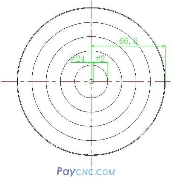
The variables set up in the figure above:
#24 Spiral interpolation cuts the tool down to the bottom plane of the hole. At this time, milling a full circle is the variable coordinate in the X direction, that is, the initial cutting point of #2.
So: #2=#24
Same as #2=#2+0.8 *#11 self-increment,
In other words, variable #2 is incremented to the size of 66.6, and the circle is processed to size.
From this, it is easy to contact the macro statements that Jun brother has said before, such as WHILE []DO statements
......
With the above simple analysis, the low plane milling procedure is as follows:
N2
#2=#24
WHILE[#2LT66.6]DO2
#2=#2+0.8*#11
IF[#2GE66.6]THEN#2=66.6
G1X#2
G3I-#2F100
END2
 |
 |
| Products Catalogue | Home | About Us | Retrofit | Download | News | Tech Support | Contact Us | |
|
|
|